FSoE-specific Properties (Safety over EtherCAT)
| Note
Refer to the PLCnext Info Center for a list of controllers supporting EtherCAT. |
| Note
The EtherCAT application needs to be installed on PLCnext Technology controllers via the PLCnext Store. |
| Note
Preconditions: The EtherCAT functionality and therefore also the EtherCAT-related PLANT nodes and editors are only available if the controller supports this (PLCnext Technology controllers from firmware version 2026.0) and the functionality has been activated in PLCnext Engineer. To do this, proceed as follows:
Furthermore, EtherCAT devices must be added to the COMPONENTS by importing the respective ESI files. Only after the ESI files have been imported are the devices available in the COMPONENTS (category 'Network | Local | Devices | ESIImport') and can be inserted in the station editor under the 'EtherCAT' node. |
EtherCAT supports safety-related communication over the standard Ethernet which is also used for non-safety-related EtherCAT communication. This is achieved by the FSoE protocol (FSoE = FailSafe over EtherCAT).
FSoE designates a safety-related communication layer with which safety-related process and parameterization data can be transferred between Safety-over-EtherCAT (FSoE) devices.
FSoE has been developed in accordance with the IEC 61508 standard and is standardized in IEC 61784-3. It meets the requirements up to SIL 3.
This topic contains the following information:FSoE frames
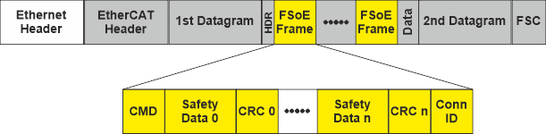
The FSoE protocol implements so-called Safety-over-EtherCAT frames which can also be considered as safety-related data containers (safety containers).
As shown in the illustration below, these frames are embedded into the process data of the cyclic EtherCAT communication: they are mapped into the cyclic EtherCAT Process Data Objects (PDOs).
An FSoE frame contains not only safety-related process and parameterization data but also information (such as checksums) that is used to check and ensure the correct transmission of safety-related data. Two bytes of safety-related data are followed by two bytes of CRC over these safety data. The amount of safety data (0 to n in the figure) is not restricted by the protocol but the slave device itself may have a restricted safety data length (which is defined in the ESI device description).
The unique connection ID (Conn ID at the end of the frame) is used by the slave to recognize that the frame is addressed to it.
Using the command (CMD) at the beginning of a frame, the FSoE master is able to control and monitor the addressed slave.
Black Channel
The underlying standard EtherCAT communication medium remains the same and transmits both safety-related and standard data. The transport medium is regarded as a Black Channel on "top" of which the FSoE protocol implements a safety-related logical data connection. This way, a decentralized safety logic can be established.
The Black Channel does not need to be considered in the safety analysis. Due to the Black Channel principle, no redundant EtherCAT ports are required in the devices involved (e.g., bus couplers). Redundant hardware, however, is required depending on the safety integration level (SIL) to be achieved.
The higher-level standard controller controls the data exchange. It can read and evaluate safety-related data transmitted in the FSoE frames. This way, data exchange between the standard and the safety-related application is possible.
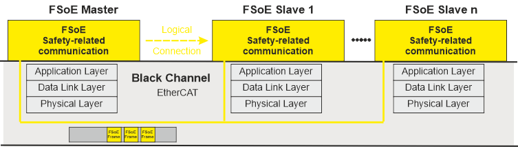
FSoE master and slaves communication
The FSoE master (Safety PLC) can manage one or several FSoE slaves. The master initiates one separate logical safety-related communication connection to each slave which has a unique connection ID. The uniqueness is checked and must be verified in order to communicate.
During the cyclical communication, the master sends FSoE master frames which contain the safety-related outputs. With sending the frame the FSoE master starts the watchdog timer. The watchdog timer monitors the communication cycles.
By means of the connection ID (inserted at the end of the frame), the addressed FSoE slave recognizes whether a frame is addressed for it. The slave reads and processes the safety-related data in the container.
After receiving a valid FSoE master frame, the FSoE slave device sends an FSoE slave frame. A slave frame contains the values, the slave read at its safety-related inputs. These input values are then received by the FSoE master and processed in the safety-related application program of the Safety PLC. The reception of the corresponding FSoE slave frame by the master confirms the master frame and the transmission is considered as valid.
After this, the cycle is completed and the watchdog is stopped. Finally, the master generates a new FSoE master frame. If the master does not receive a valid slave frame within the set watchdog interval, an error occurs.
FSoE slave addressing
Each FSoE slave has a slave address which is unique within the EtherCAT network. The slave address consists of 16 bits which allow the addressing of a maximum of 65534 slaves (address 0xFFFF is reserved).
The slave address is assigned automatically when inserting devices into the PLANT in PLCnext Engineer. The address can be adjusted, for example, using a DIP switch on the device or a configuration editor.
After modeling the Safety over EtherCAT network in the PLANT, you must make sure that the addresses set at the slaves match the addressing in PLCnext Engineer.
Implementation in PLCnext Engineer
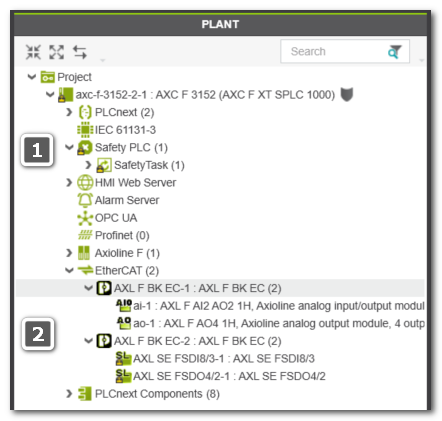
In the PLANT, the FSoE safety application is represented by the following nodes:
(The numbers in the list refer to the example PLANT shown below.)
| Note
To edit the safety application, you have to be logged on to the Safety-Related Area. |
- (1): Safety PLC which executes the safety-related application and implements the FSoE master.Available FSoE-related editors for the master:
- 'Safety Cockpit' - provides access to control and monitoring commands and displays diagnostic information.
- 'Settings' editor - used to specify which FSoE-specific system variables should be created.
See topic "Diagnostic FSoE system variables - Enabling the Creation" for details. - 'Tasks and Events' editor - used to set the cycle time of the Safety Task and define the communication watchdog interval. See topic "Safety PLC Runtime Configuration". The set watchdog time influences the maximum Safety Function Response Time (SFRT).
- FSoE slaves under the 'EtherCAT' node.(2): EtherCAT: I/O slaves must be connected to a bus coupler. As the bus coupler is transparent in safety-terms, a standard bus coupler can be used. Standard and safety I/O modules can be mixed here.Available FSoE-related editor for slaves: The 'Safety Parameters' editor is used to parameterize the FSoE slave.
Note
You can insert modules either via the station editor ('Module List' editor of the bus controller node) or via drag & drop.
Example:
What do you want to do?
 Enable the creation of diagnostic FSoE system variables
Determine the Safety Function Response Time (SFRT)
Edit parameters of safety-related devices ('Safety Parameters' editor)